About Trinamic
- Based in Hamburg, Germany
- TRINAMIC provides integrated Circuits and Modules for Motor and Motion Control to customers all over the world, most of them leaders in their Industry
Application driven
- The use of small motors is increasing rapidly in many different types of products
- In leading-edge industries such as biotechnology, lab automation, semiconductor handling equipment, CCTV and factory automation,
TRINAMIC products control all kinds of embedded motion control systems
- TRINAMIC’s application-driven approach and deep application understanding means that customers do not need in-depth knowledge of motors, nor of control circuitry
- Consequently, the design phase is simplified, resulting in significant labor and cost savings in development as well as a reduction in the total cost of ownership
Ease of Use
- TRINAMIC’s Motion Control Language (TMCL) makes it easy to develop motion control applications and allows for
shorter development cycles and a short time to market
- TRINAMIC customers benefit from the company’s extensive knowledge of motor physics and its library of intellectual property (IP), built over years of application knowledge
- Product development at TRINAMIC focuses on meeting customer demands for miniaturization, efficiency, diagnostic support and protection, all of
which ensure the reliability of the complete system
Energy Efficiency
- TRINAMIC is committed to energy efficient solutions
- With industry leading technologies such as the patented coolStep™, TRINAMIC products add energy-saving to the ease of use and precision of
stepper Motors
- The patented stallGuard2™ load detection enables precise and silent homing without any homing switches
- Integrated diagnostic features can detect potential system faults to reduce downtime
German Engineering
- TRINAMIC cherishes the core values of German engineering and is committed to reliability, not only concerning the products, but also with regard to business ethics and processes


- TRINAMIC is certified according to ISO9001 and ISO13485 (medical components)
- Embedded in a network of strong strategic relationships with leading research institutions and industrial partners, TRINAMIC’s research efforts
are superior, geared entirely to the enhancement of product performance, to innovation and invention, at the same time increasing efficiency and reducing power consumption
Long Term Commitment
- With a history going back more than 20 years and a traditional private ownership of the company shares, TRINAMIC is able to give a commitment to long term availability
- Headquartered in Hamburg, Germany, TRINAMIC products are sold via a global distribution network
New Products
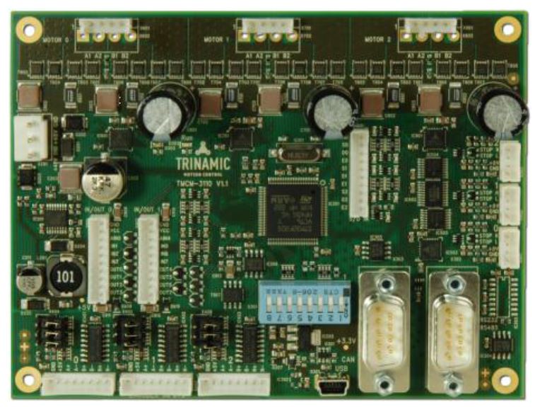
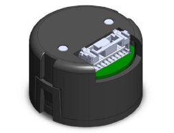
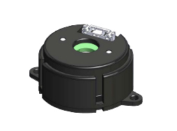
TMCM-1321: Stepper Motor Closed-Loop Controller & Driver 0.7A/24V with RS485, 28x28
The TMCM-1321 is an easy to use, single axis controller/driver for 2-phase bipolar stepper motors with separate home and stop switch inputs.
The built-in magnetic encoder can be used when a suitable magnet is attached to the motor axis, enabling also closed-loop operation.


Working from a single or dual Li-Ion cell or dual or more AA batteries the TMC7300 is optimally suited for battery operated equipment. Its two full-bridges allow either control
of two DC motors, PWM-control of LEDs, or protected standalone peripheral driving, using a polarity signal per halfbridge.
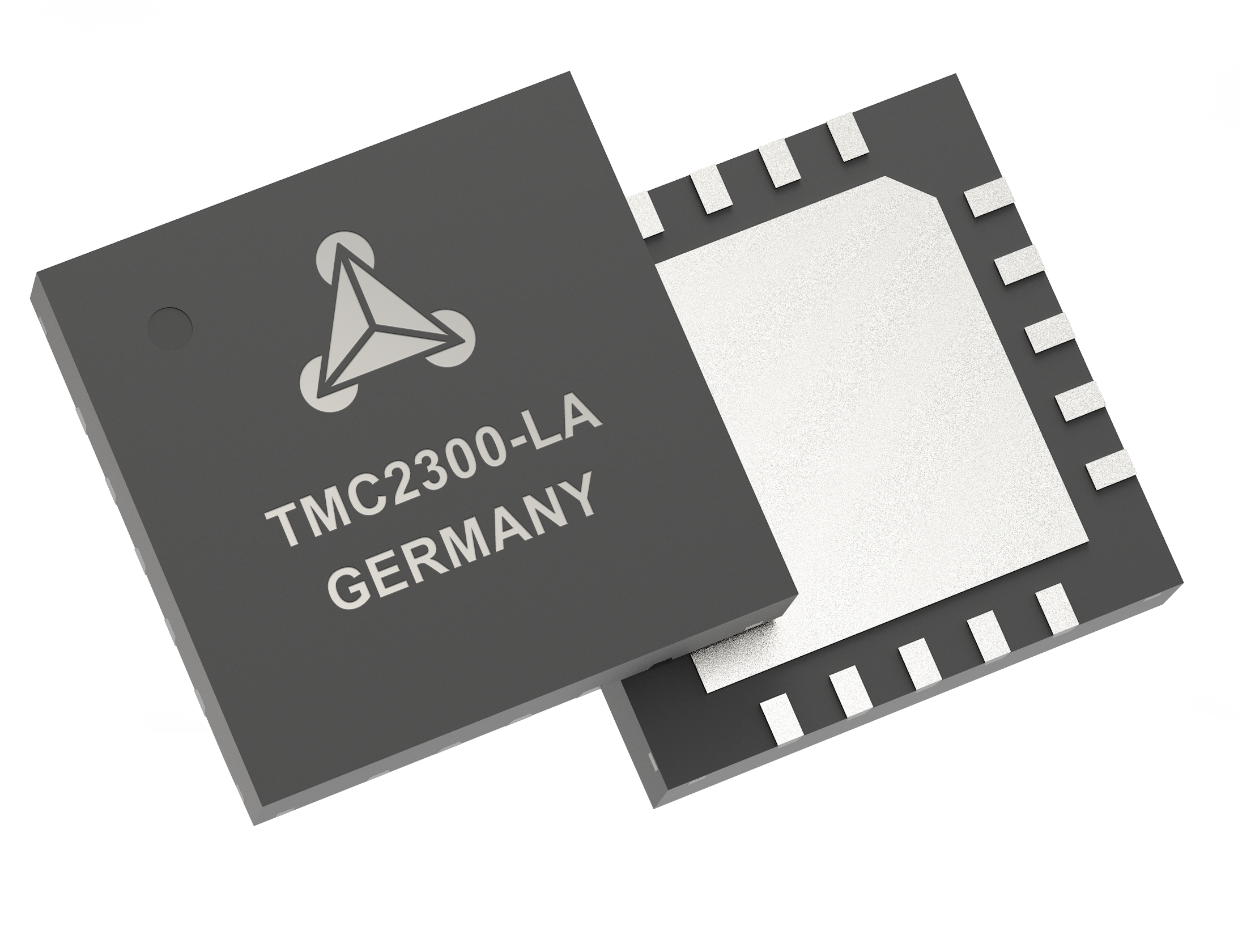
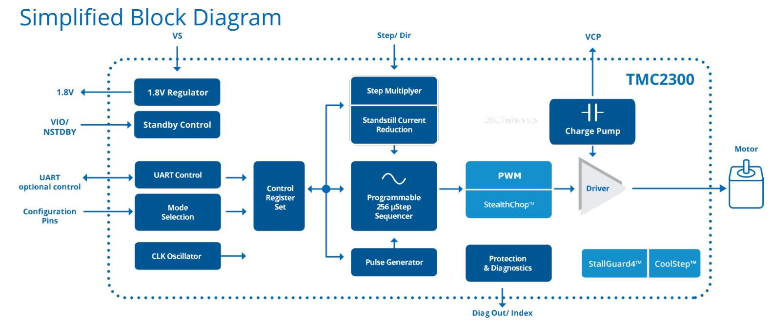
The TMC2300 low voltage stepper motor driver is intended for battery-operated, space and standby-power critical driver applications.
Its silent drive technology StealthChop™ enables non-bugging motion control for portable, home and office applications.
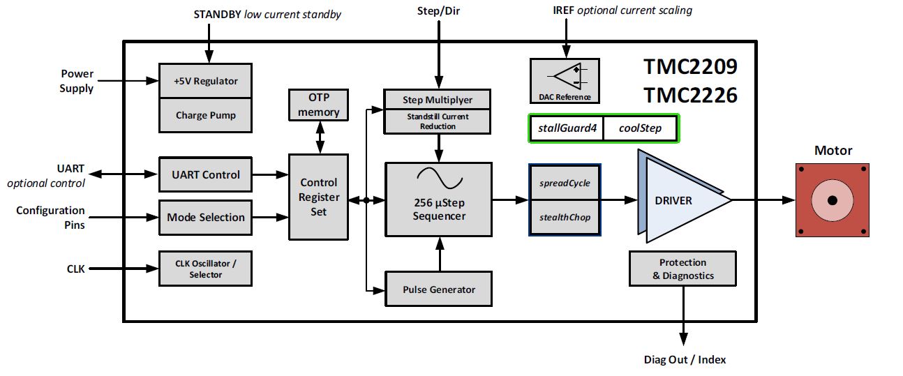
Very low cost stand-alone stepper motor driver with fast acceleration stealthChop2 (no noise) and sensorless load detection.
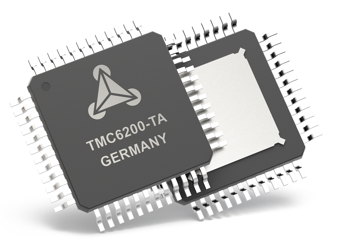
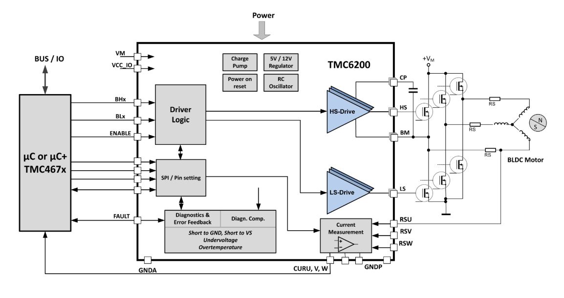
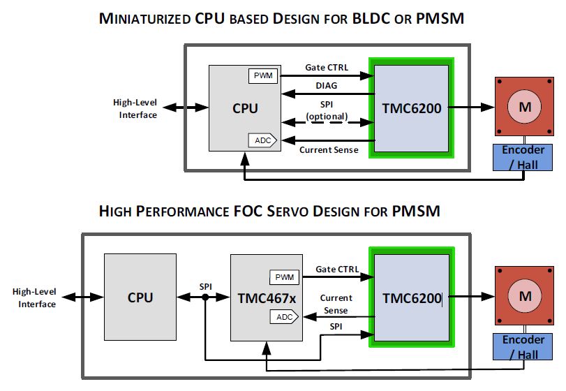
The TMC6200 is a high-power gate driver for PMSM servo or BLDC motors. Using six external MOSFETs and two or three sense resistors,
it integrates the full high voltage part of a FOC drive system for 12V, 24V or 48V, including in-line current sense amplifiers with programmable amplification.
- 3 floating Sense Amplifiers with programmable gain
- up to 60V
- programable gate current: 0,5A | 1A | 1,5A
- perfect fit with TMC4671
Stepper Motor Driver ICs
Stand Alone Drivers
"Stand Alone" stepper motor driver do not need a serial interface. The common interface for this easy to use drivers is "Step/Direction" (SD).
Some divers can be uses in different modes: "Stand Alone", "Smart" & "Controller + Driver".
 |

Product Guide Integrated Circuits |
| P/N |
Axes |
Voltage |
Current
(rms)
(peak) |
Interface |
max
µStep
Res. |
Features |
Eval Board |
Datasheet
/Web |
TMC2300-LA
|
1 |
1,8...11V |
2,0A |
Step/Dir
( UART ) |
256 |
diagnosis & protection
spreadCycle™
StallGuard4™
stealthChop2™ |
TMC2300-Eval
 |

|
TMC2209-LA /
TMC2226-LA
|
1 |
4,75 ... 29V |
2A
2,8A |
Step/Dir
( UART ) |
256 |
diagnosis & protection
spreadCycle™
StallGuard4™
stealthChop2™ |
TMC2209-EVAL
|
|
TMC2208-LA
TMC2224-LA
TMC2202-WA
 |
1 |
4,75...36V |
1,2A
1,7A |
Step/Dir
( UART ) |
256 |
High Volume / Low Cost
(MOQ = 3k)
Pin compatibility:
TMC2208 -> A4988
TMC2224 -> DRV8824
diagnosis & protection
spreadCycle™
stealthChop2™
Wettable Flanks -> TMC2202 |
TMC2208-EVAL
TMC2224-EVAL
|
|
TMC2100-LA
TMC2100-TA
 |
1 |
4,75...46V |
1,2A
1,7A |
Step/Dir |
256 |
diagnosis & protection
spreadCycle™
microPlyer™
stealthChop™ |
TMC2100-EVAL
|
|
TMC2160
 |
1 |
8...60V |
(up to 20A)
ext.
MOSFETs |
Step/Dir
(SPI) |
256 |
diagnosis & protection
spreadCycle™
microPlyer™
stealthChop2™ |
TMC2160-EVAL
|
|
 Evalboards
Datasheets
Highlight: TMC2300 (1,2A/11V)
Low voltage stepper motor driver with silent drive technology stealthChop and highly efficient power stage
Evalboard: TMC2300-EVAL /-KIT
Datasheet: TMC2300
Highlight: TMC2209 / TMC2226 (1,9A/29V)
Very low cost stand-alone stepper motor driver with fast acceleration stealthChop2 (no noise) and sensorless load detection
Evalboard: TMC2209-EVAL /-KIT
Datasheet: TMC2209
Smart Drivers
"Smart Driver" have an integrated serial interface for setting the parameters and to get feedback for diagnosis and advanced options. Common serial interfaces are SPI™ or single wire UART.
| P/N |
Axes |
Voltage |
Current
(rms)
(peak) |
Interface |
max
µStep
Res. |
Features |
Eval Board |
Datasheet
/Web |
TMC2209-LA /
TMC2226-LA
|
1 |
4,75 ... 29V |
2A
2,8A |
Step/Dir
( UART ) |
256 |
diagnosis & protection
spreadCycle™
StallGuard4™
stealthChop2™ |
TMC2209-EVAL
|
|
TMC2208-LA
TMC2224-LA
TMC2202-WA
|
1 |
4,75...36V |
1,2A
1,7A |
Step/Dir
UART |
256 |
High Volume / Low Cost
(MOQ = 3k)
Pin compatibility:
TMC2208 -> A4988
TMC2224 -> DRV8824
diagnosis & protection
spreadCycle™
stealthChop2™
Wettable Flanks -> TMC2202 |
TMC2208-EVAL
TMC2224-EVAL
|
|
TMC2100-LA
TMC2100-TA
|
1 |
4,75...46V |
1,2A
1,7A
-
1,4A
2,0A |
Step/Dir |
256 |
diagnosis & protection
spreadCycle™
microPlyer™
stealthChop™ |
TMC2100-EVAL
|
|
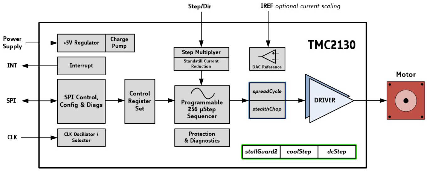
TMC2130-LA
TMC2130-TA
 |
1 |
4,75...46V |
1,2A
1,7A
-
1,4A
2,0A |
SPI
Step/Dir |
256 |
diagnosis & protection
stallGuard2™
coolStep™
spreadCycle™
microPlyer™
dcStep™
stealthChop™ |
TMC2130-EVAL
|
|
TMC2160
 |
1 |
8...60V |
(up to 20A)
ext.
MOSFETs |
SPI
Step/Dir |
256 |
diagnosis & protection
stallGuard2™
coolStep™
spreadCycle™
microPlyer™
stealthChop2™ |
TMC2160-EVAL
|
|
TMC2041-LA
 |
2 |
4,75...28V |
2x 1,1A
2x 1,5A |
SPI
Step/Dir |
256 |
diagnosis & protection
stallGuard2™
coolStep™
spreadCycle™
microPlyer™
stealthChop™ |
TMC2041-EVAL
|
|
Highlight: TMC2130 (1,2A/46V)
Low cost smart stepper motor driver with serial interface with stealthChop (no noise)
Evalboard: TMC2130-EVAL/-KIT
Datasheet:
TMC2130
Highlight: TMC2160 for external MOSFETs (20A/60V)
The TMC2160 is a high power smart stepper motor driver IC with serial communication interfaces. Using external transistors, highly
dynamic, high torque drives can be realized. Based on TRINAMICs sophisticated spreadCycle and stealthChop choppers, the driver ensures
absolutely noiseless operation combined with maximum efficiency and best motor torque. High integration, high energy efficiency and a small form
factor enable miniaturized and scalable systems for cost effective solutions.

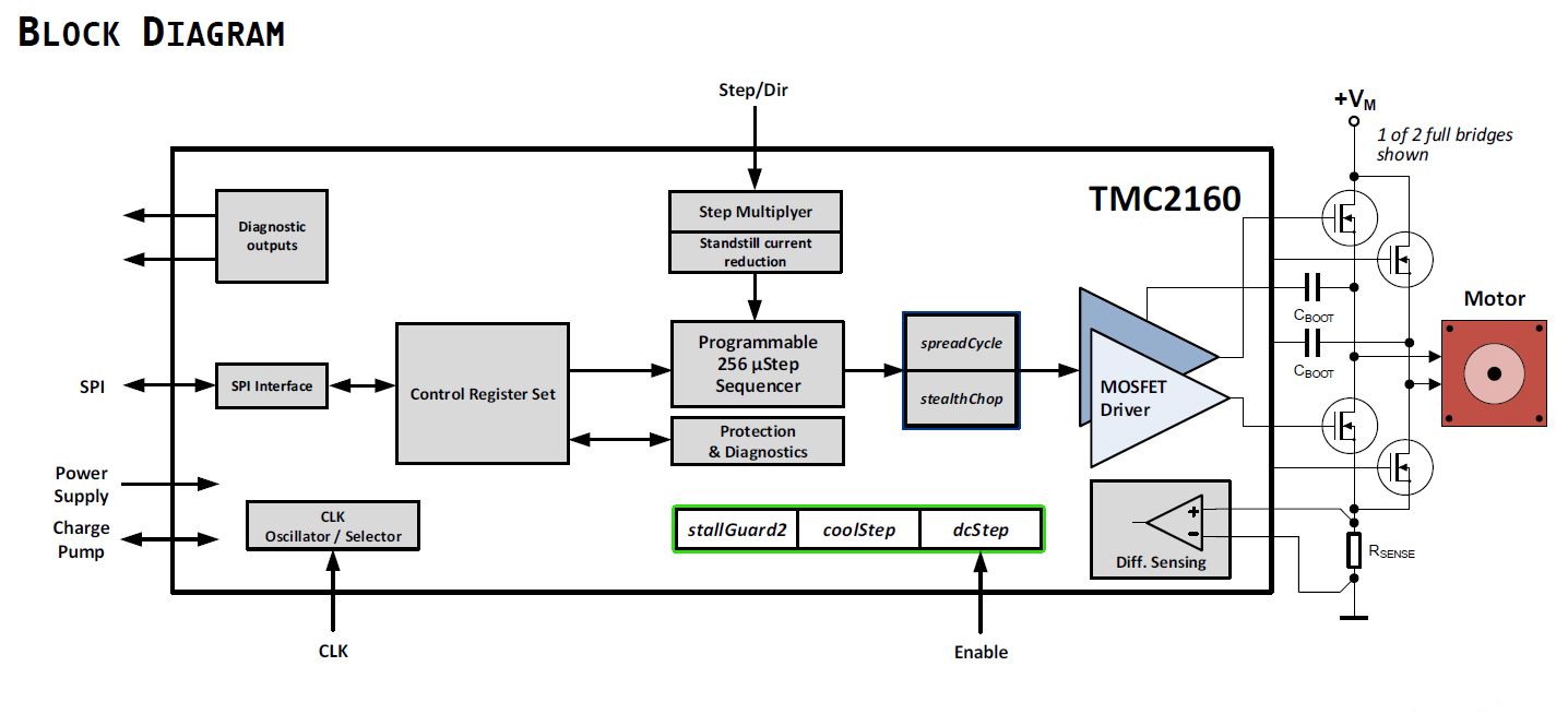
Key features:
- no noise & high acceleration (stealthChop2)
- smooth movement
- up to 60V and 20A
- differential current sensing
- similar to TMC2130
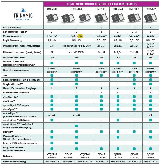
Motion Controller & Driver (cDriver)
| P/N |
Axes |
Voltage |
Current
(rms)
(peak) |
Interface |
max
µStep
Res. |
Features |
Eval Board |
Datasheet
/Web |
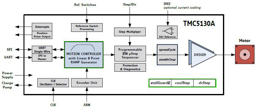
TMC5130-TA

|
1 |
4,75..46V |
1,4A
2,0A |
SPI
Step/Direction
single wire UART
ABN Encoder
2x ref.-switch |
256 |
diagnosis & protection
stallGuard2™
coolStep™
spreadCycle™
microPlyer™
dcStep™
stealthChop™ |
TMC5130-EVAL
|
|
TMC5160-TA
TMC5160-WA
|
1 |
4,75..60V |
up to 20A
with
external
MOSFETs |
SPI
Step/Direction
single wire UART
ABN Encoder
2x ref.-switch |
256 |
diagnosis & protection
stallGuard2™
coolStep™
spreadCycle™
microPlyer™
dcStep™
stealthChop2™ |
TMC5160-EVAL
TMC5160-BOB
|
|
TMC5161-AA
 |
1 |
8..40V |
3.5A |
SPI
Step/Direction
single wire UART
ABN Encoder
2x ref.-switch |
256 |
diagnosis & protection
stallGuard2™
coolStep™
spreadCycle™
dcStep™
stealthChop2™ |
TMC5161-EVAL
|
|
TMC5031-LA
 |
2 |
4,75..16V |
2x 1,1A
2x 1,5A |
SPI
4x ref.-switch |
256 |
diagnosis & protection
stallGuard2™
coolStep™
spreadCycle™
microPlyer™ |
|
|
TMC5041-LA
 |
2 |
4,75..28V |
2x 1,1A
2x 1,5A |
SPI
4x ref.-switch |
256 |
diagnosis & protection
stallGuard2™
coolStep™
spreadCycle™
microPlyer™
stealthChop™ |
TMC5041-EVAL
|
|
TMC5062-LA
 |
2 |
4,75..20V |
2x 1,1A
2x 1,5A |
SPI
single wire UART
2x ABN Encoder
4x ref.-switch |
256 |
diagnosis & protection
stallGuard2™
coolStep™
spreadCycle™
microPlyer™
dcStep™
3Phase Stepper |
TMC5062-EVAL
|
|
TMC5072-LA
 |
2 |
4,75..28V |
2x 1,1A
2x 1,5A |
SPI
Step/Direction
single wire UART
2x ABN Encoder
4x ref.-switch |
256 |
diagnosis & protection
stallGuard2™
coolStep™
spreadCycle™
microPlyer™
dcStep™
stealthChop™
|
TMC5072-EVAL
|
|
Evalboards
Datasheets
Highlight: TMC5130 (1,4A/46V)
Low cost stepper motor cDriver with serial interface with stealthChop (no noise)
Stepper Motion Controller ICs
The Motion Controller ICs include the pulse and ramp generation as well as the position controller.
 |
Product Guide Integrated Circuits |
Evaluation-Boards
Datasheets
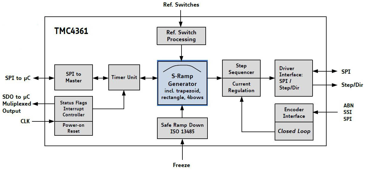
Highlight: TMC4361 Closed Loop Motion Controller (Squirrel)
The TMC4361 is intended for applications where a fast and jerk-limited motion profile is desired. This motion controller adds to any
microcontroller with SPI interface. It supports S-shaped, trapezoid, and rectangular ramps.
With encoder, the TMC4361 allows for an extremely quick and precise positioning. Its servo features provide step loss protection, energy
efficiency, and target positioning with stepper typical stability.
Standard SPI and STEP/DIR interfaces to the motor driver simplify communication. High end features,no software effort and the small form
factor of the TMC4361 enable miniaturized designs with low external component count for cost-effective and highly competitive solutions.
BLDC ICs
Product Guide Integrated Circuits |

BLDC Overview |
| P/N |
Axes |
Voltage |
Interface |
Features |
Eval Board |
Datasheet
/Web |
TMC4671-LA
 |
1 |
1,95V
+
3,3V |
SPI
Step/Dir
PWM
ABN
HALL
Analog |
Servo Controller & Field oriented Control
|
TMC4671-EVAL
|
|
TMC6200-TA
 |
1 |
8...60V |
PWM
SPI
Error
|
prog. gate current 0,5 / 1 / 1,5A
3x inline current amplifiers |
TMC6200-EVAL
|
|
TMC6100-LA
 |
1 |
8...60V |
PWM
SPI
Error |
3-phase motors up to 100A coil current (external MOSFETs)
prog. gate current 0,5 / 1 / 1,5A |
|
|
TMC6300-LA
 |
1 |
2..11V |
PWM |
Direct Bridge control for BLDC or PMSM sine-commutation
Optimally suited for battery operated equipment
|
|
|
Evalboards
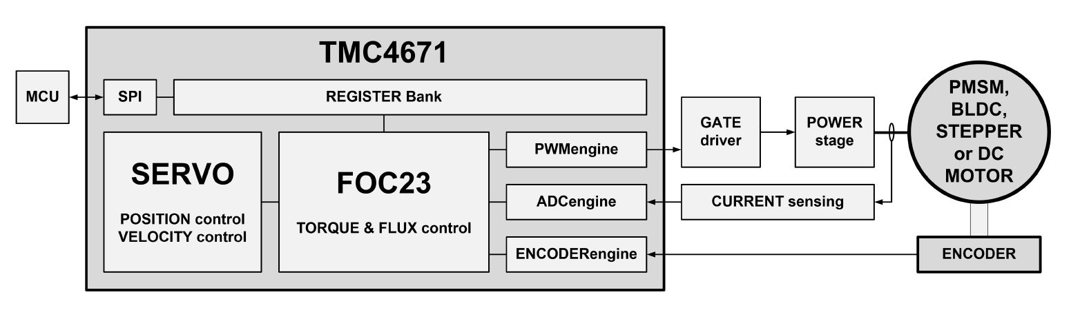
The world’s first fully integrated servo controller IC providing field-oriented control for BLDC/PMSM and 2-phase stepper motors, as well as DC motors and voice coils.
The TMC4671 is designed to rapidly decrease time to market for highly performant servo controllers while maximizing drive efficiency as well as dynamics.
With all time critical calculations in hardware, just a few lines of code are necessary to develop a dynamic servo controller.
It offers high switching frequency and controller update rates of up to 100kHz and has filtering and interpolation features like the digital Hall signal
interpolation for smoother operation. The IC can work with various encoders such as simple digital or analog Hall sensors over A/B/Z incremental and
high-resolution sin/cos analog encoders. Sensors can be flexibly mapped as an input for position and velocity control loops. With its delta sigma
current sensing ADCs, the TMC4671 is perfectly suited for isolated delta sigma frontends.
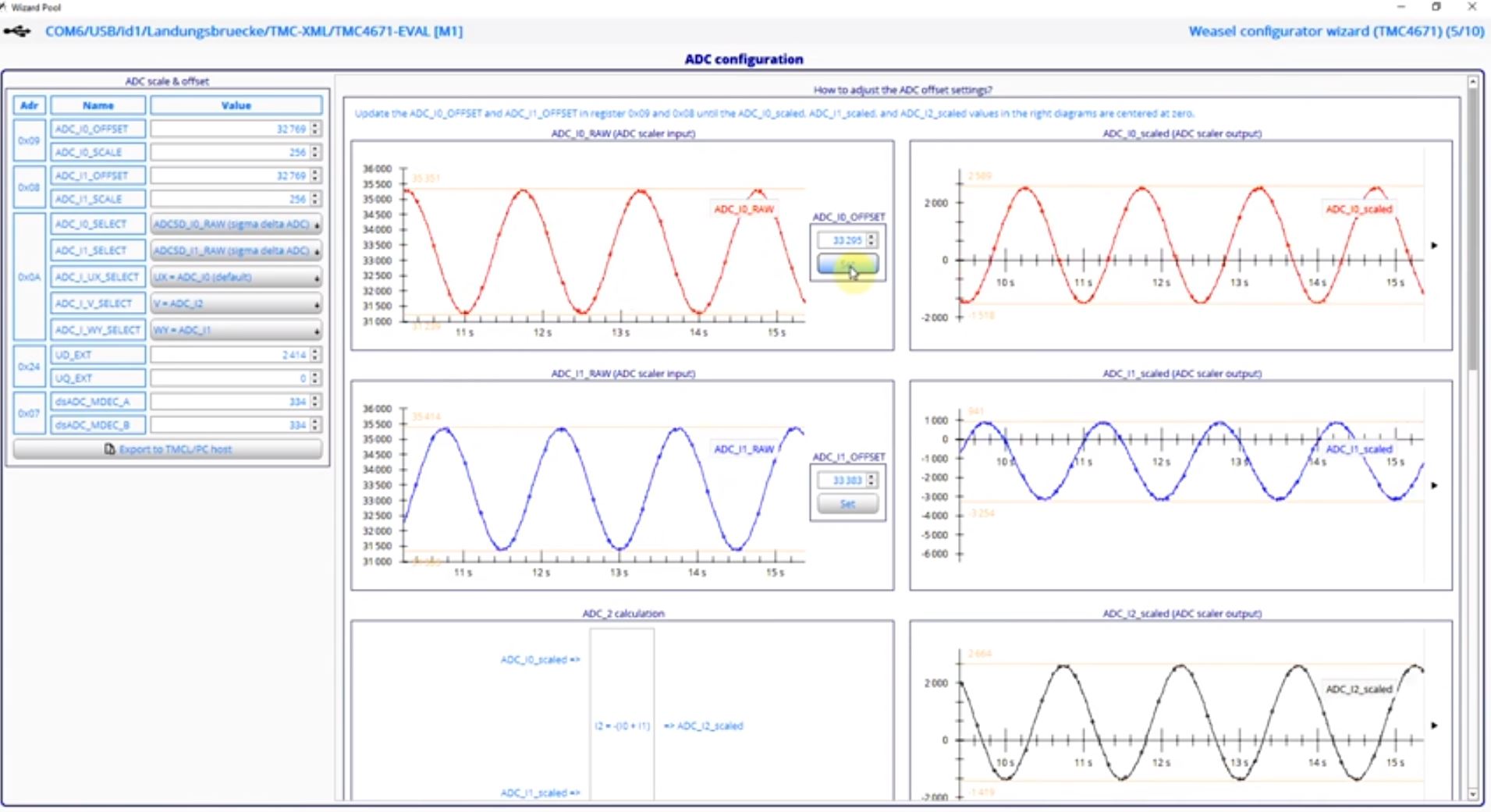
A Real Time Monitoring Interface (RTMI) is available for configuration and optimazition of the controller together with a comprehensive IDE software for Win PC.
DC-Driver-ICs
Product Guide Integrated Circuits |
| P/N |
Axes |
Voltage |
Interface |
Features |
Eval Board |
Datasheet
/Web |
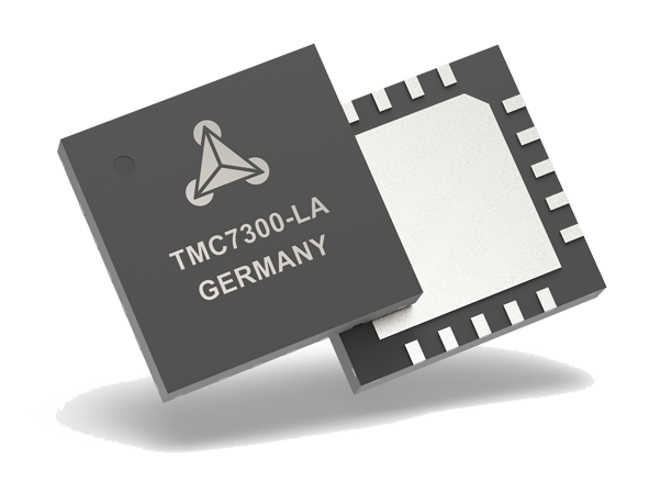
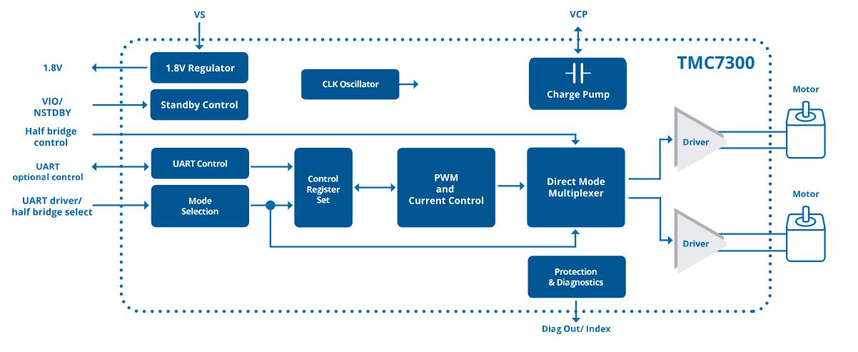
TMC7300-LA
|
2 |
2...11V |
single wire UART |
Direct Bridge: control for solenoids, relays, lamps, motors…
Standby: <50nA typ. current draw
Low RDSon: LS 170mΩ & HS 170mΩ (typ.)
Parallel Option: for single DC motor
Full Protection & Diagnostics
|
|
|
Highlight: TMC7300 Low Voltage Dual DC-Motor Driver with UART (2x1,2A/2..11V)
Working from a single or dual Li-Ion cell or dual or more AA batteries the TMC7300 is optimally suited for battery operated equipment. Its two full-bridges allow either control
of two DC motors, PWM-control of LEDs, or protected standalone peripheral driving, using a polarity signal per halfbridge. Operate up to two DC motors via simple UART control
for direction, velocity and torque. Integrated power-MOSFETs with internal charge-pump for best-in-class RDSon even at low supply voltage, handle motor current up to 1.2A per motor
continuously, or the double current in parallel connection. Together with a tiny standby current, this guarantees a long battery life. Protection and diagnostic features support
robust and reliable operation. This advanced driver ensures efficient and reliable operation for cost-effective and highly competitive solutions.
Interface-Controller ICs
EtherCAT Slave Controller

TMC846x is a family of EtherCAT slave controller IC. Besides the slave controller with its proven conformance to the EtherCAT standard they come
with a sophisticated multifunction I/O block (MFCIO) optimized for embedded motion- and motor control applications.
Key points:
- 100% Beckhoff compatible (Beckhoff code)
- Beckhoff licence clearing done by Trinamic
- TMC8462 with integrated PHYs: smallest available solution (9x9mm)
- integrated Multi Function and Control I/O Block (MFCIO) for Motion Control or Sensors
The MFCIO may be accessed directly from the EtherCAT bus or via SPI-Interface from the local host MCU.
Presentation:
ProductPresentation_TMC846x-EtherCAT-Family
Product Flyer:
TMC846x-Family-Flyer
Product Guide:
Integrated Circuits
| P/N |
Interfaces |
Features |
Package |
Datasheet
/Web |
TMC8461
| 2x MII (PHY)
IIC
SPI Master Interface
ABN encoder IN (differential)
3x Step/Direction OUT
4x PWM OUT
1x DAC OUT
24x Multi Function I/O
8x 100mA HV I/Os |
EtherCAT slave controller
with latency free I/O peripherals
8x FMMU
8x Syncmanager
16k Process Data RAM
64bit Distributed Clocks
30Mbit/s SPI Process Data Interface
16/25MHz Clock Output |
LGA144
10x10mm
0,8mm
pitch |
|
| TMC8462 |
2x PHY
IIC
SPI Master Interface
ABN encoder IN (differential)
3x Step/Direction OUT
4x PWM OUT
1x DAC OUT
24x Multi Function I/O
8x 100mA HV I/Os |
EtherCAT
slave controller
with latency free I/O peripherals
and integrated PHYs
8x FMMU
8x Syncmanager
16k Process Data RAM
64bit Distributed Clocks
30Mbit/s SPI Process Data Interface
16/25MHz Clock Output |
LGA121
9x9mm
0,75mm
pitch |
|
TMC846x Family are the first EtherCAT slave controller ICs to incorporate PWM and Step/Dir I/O peripherals that do not require routing
through the firmware of an application processor, eliminating latency for applications requiring real-time response. The TMC8460 extends the feature
set of the core EtherCAT technology with a broad array of peripherals and features: an integrated smart peripherals block accessible from an MCU or
EtherCAT master and, in addition to a PWM unit and Step/Dir interface, an SPI master and encoder interface that can be directly mapped to the PDO
(Process Data Object) by the memory manager. This unique SPI interface enables latency-free read from an ADC or write to a DAC.
The IC includes a standalone mode that enables direct mapping of integrated peripherals to bus registers, while in parallel an external MCU can perform
higher layer protocol operations. To enable wide interoperability, the TMC8460 communication hardware has been verified as 100% compatible with the
existing Beckhoff EtherCAT Slave controller through extensive interoperability testing.
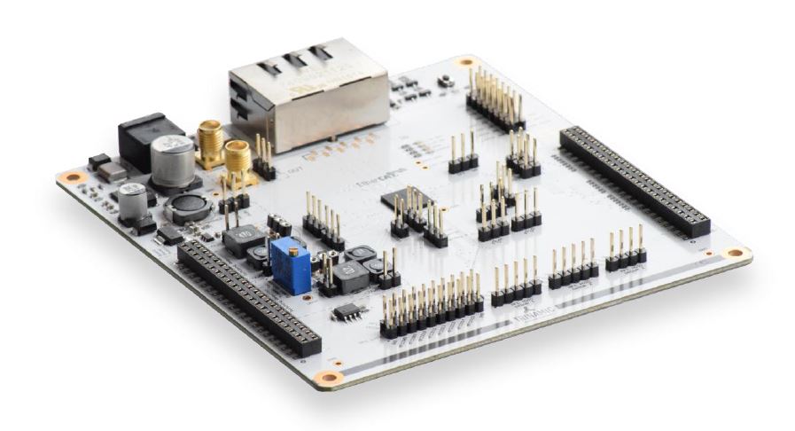
Evalboard: TMC8462-EVAL
Application Diagrams
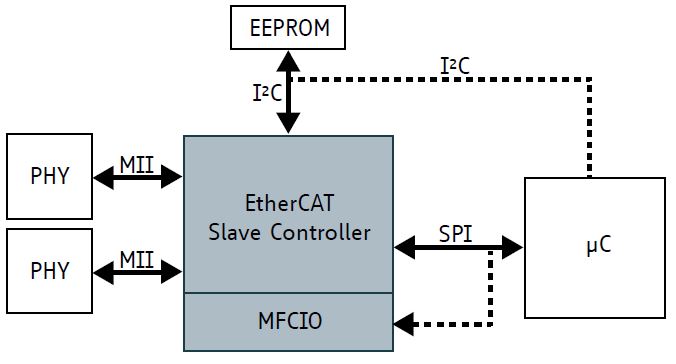
Application with MCU and MFCIO
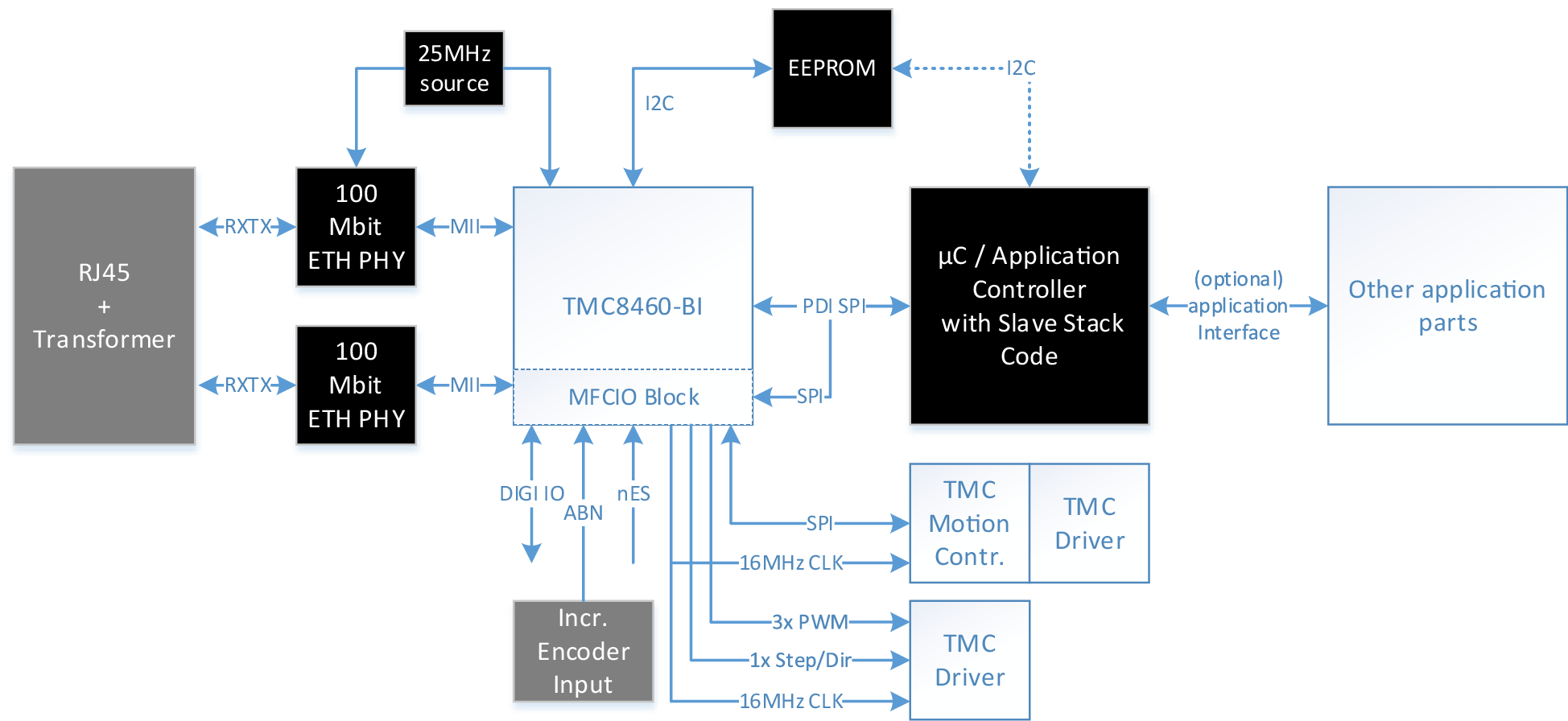
Application diagram using the MFCIO block features to reduce software overhead and provide real-time hardware support to the MCU. Other application parts may still be connected to the MCU.
Application with MCU without MFCIO
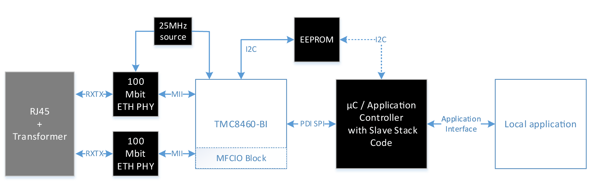
Application diagram using only the local application controller to interface the application
Application with MFCIO without MCU (simple slave)
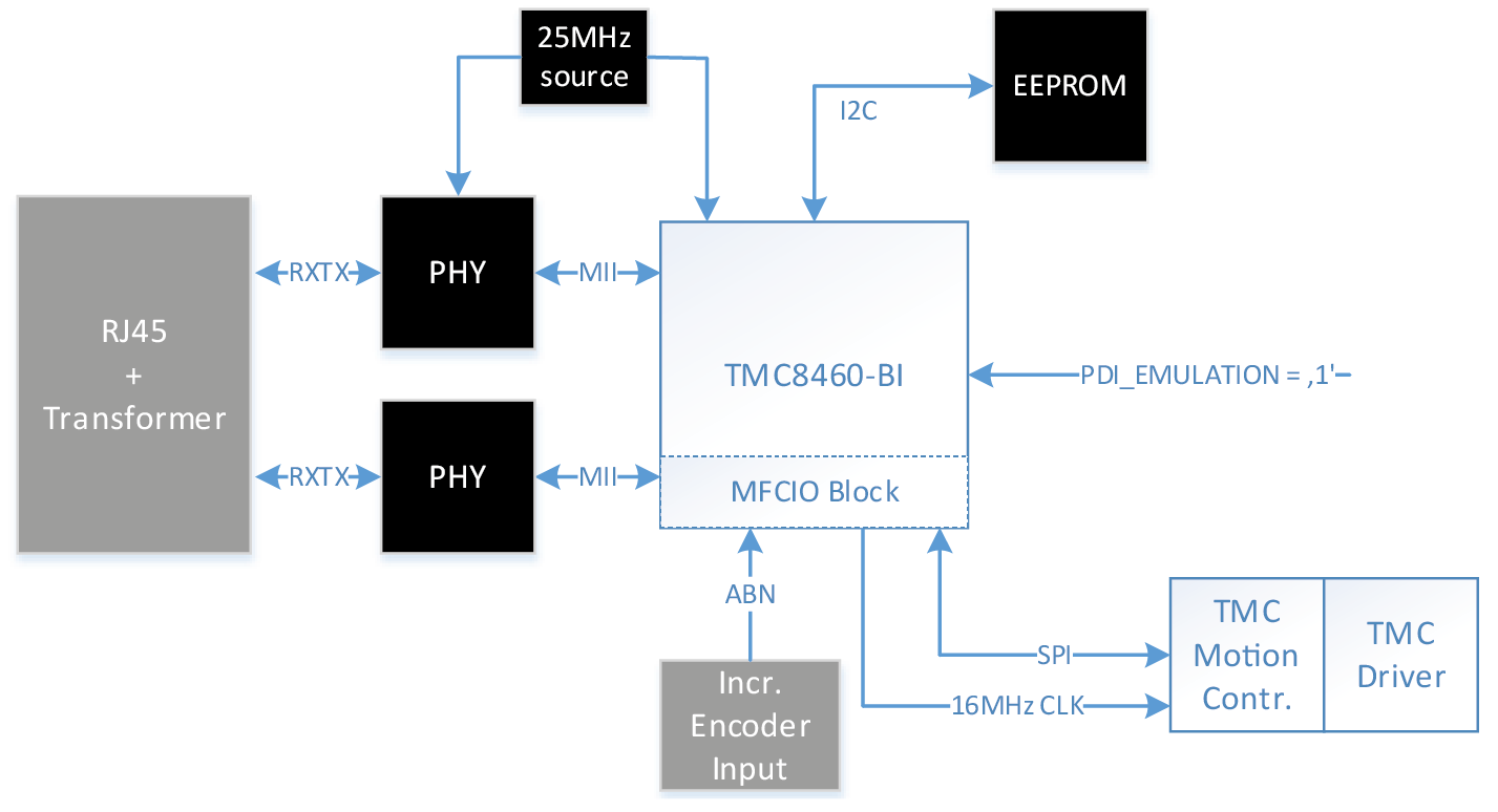
Application diagram without MCU. The TMC8460 is used in device emulation mode. SPI slave chips and other application peripherals can be connected to
the MFCIO block. The EtherCAT master can directly control all the application functions.
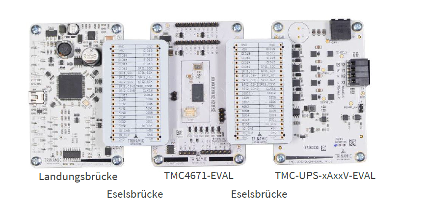
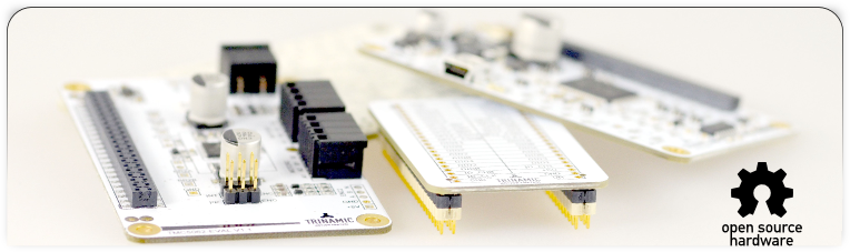
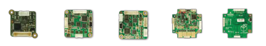
Evaluation Boards
Trinamic’s new Evaluation Board system allows users to freely combine several evaluation boards for Trinamic products into a single kit, enabling
easy development of comprehensive solutions for controlling and driving electric motors.
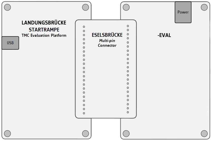
A kit can contain:
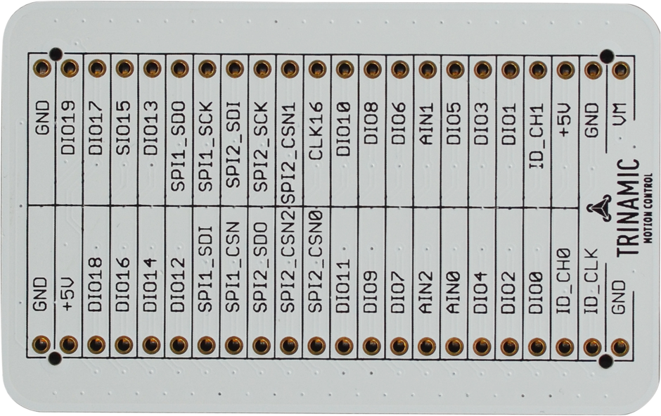
• one interface board "Startrampe" or "Landungsbrücke"
• one or two connector boards "Eselsbrücke"
• one motion controller board
• one driver board
• one or two motors
The kits allow users to interchange single boards to examine different combinations of Trinamic ICs, or to integrate the Evaluation Board with your own setup.
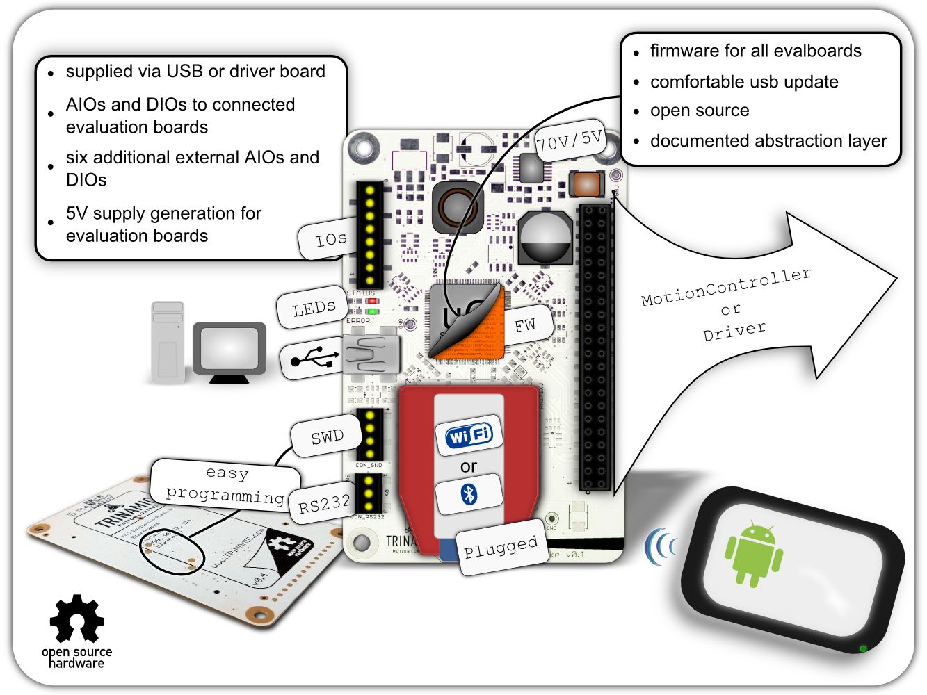
The controller board "Startrampe" or "Landungsbrücke" is the connection between your desktop computer and Trinamic’s Chip solutions. Just connect
the desired board combination and start to discover Trinamic’s unique features.
"Startrampe" and "Landungsbrücke" is designed for intuitive, multipurpose usage. Like all boards in Trinamic’s evaluation system, it is
built to be flexible, rugged and affordable. With its rugged and affordable design an evaluation board can also be used if rapid product deployment is required.
A single firmware design covers all evaluation boards of the Trinamic evaluation system. Users can download the latest revisions, modify the
firmware or create your own and easily update it via USB. The code is open source for download.
Presentation: TMC-Landungsbrücke
Evaluationsystem of TMC4671-ES FOC Controller
| P/N |
used ICs |
Voltage
&
Current
(rms) |
EVK
Price
Board |
Price
Kit |
Datasheet
/Web |
Startrampe
Controller board for Win-PC
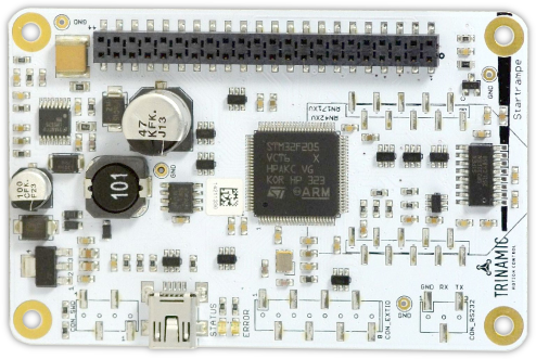 |
STM F205
Cortex M3 |
5..70V |
75€ |
n.a. |
n.a. |
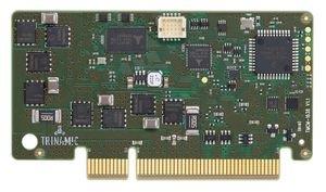
Landungsbrücke
Controller board for Win-PC
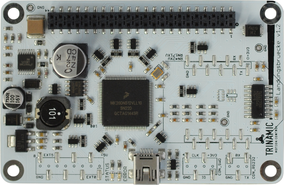 |
Freescale
M20
Cortex M4 |
5..70V |
75€ |
n.a. |
|
Eselsbrücke
Connection board
 |
no |
n.a. |
|
n.a. |
n.a. |
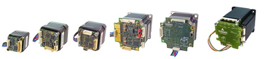
Stepper Modules
Stepper Modules: Motor Mountable
Family Properties:
- max. µStep Resolution: 256
- single axis
- mountable on NEMA stepper motors
- TMCL Trinamic Motion Control Language
|
Product Guide Embedded Modules |
| P/N |
Interface |
Voltage |
Phase
Current
(rms) |
Ramp |
max
µStep
Res. |
Encorder
Input |
Features |
FW
option* |
Motor
Size |
Datasheet
/Web |
| TMCM-1210 |
RS485
|
7...30V |
0,6A |
sixPoint™ |
256 |
- |
stallGuard2™
coolStep™
spreadCycle™
stealthChop™
microPlyer™ |
- |
NEMA8
20x20mm |
|
| TMCM-1021 |
RS485
Step/Dir |
9...28V |
0,7A |
linear |
256 |
- |
stallGuard2™
coolStep™
spreadCycle™
microPlyer™ |
- |
NEMA11
28x28mm |
|
TMCM-1140
|
CAN
RS485
USB |
9...28V |
2,0A |
linear |
256 |
ABN |
stallGuard2™
coolStep™
spreadCycle™ |
-TMCL
-CANopen |
NEMA17
37x37mm |
|
TMCM-1141
|
RS485
USB
Step/Dir |
9...28V |
1,1A |
linear |
256 |
- |
stallGuard2™
coolStep™
spreadCycle™
microPlyer™ |
- |
NEMA17
37x37mm |
|
| TMCM-1240 |
CAN
RS485
USB
Step/Dir |
10...30V |
2,0A |
linear
SixPoint™ |
256 |
ABN |
stallGuard2™
coolStep™
spreadCycle™
stealthChop2™
microPlyer™ |
-TMCL CANopen |
NEMA17 37x37mm |
|
TMCM-1160
|
CAN
RS485
USB
Step/Dir |
9...51V |
2,8A |
linear |
256 |
ABN |
stallGuard2™
coolStep™
spreadCycle™
microPlyer™ |
-TMCL
CANopen |
NEMA23/24
60x60mm |
|
TMCM-1161
|
RS485
USB
Step/Dir |
10...30V |
2,8A |
linear |
256 |
- |
stallGuard2™
coolStep™
spreadCycle™
microPlyer™ |
- |
NEMA23/24
60x60mm |
|
TMCM-1260
|
RS485
USB
CAN
Step/Dir |
12...54V |
6A |
linear
SixPoint™ |
256 |
ABN |
stallGuard2™
coolStep™
spreadCycle™
stealthChop2™
microPlyer™ |
-TMCL
CANopen |
NEMA23/24
60x60mm |
|
TMCM-1180
|
CAN
RS485
RS232
USB
Step/Dir |
18...55V |
5,5A |
linear |
256 |
ABN |
stallGuard2™
coolStep™
spreadCycle™
microPlyer™ |
-TMCL
CANopen |
NEMA34
86x86mm |
|
| TMCM-1110 |
CAN
RS485
USB
Step/Dir |
10...30V |
2,8A |
linear |
256 |
ABN |
stallGuard2™
coolStep™
spreadCycle™
microPlyer™ |
- |
- |
|
| TMCM-1312 |
RS485 |
9...28V |
0,7A |
linear
S-shaped |
256 |
ABN |
stallGuard2™
coolStep™
spreadCycle™ |
- |
NEMA 11
28 x 28mm |
|
*TMCM Modules without FirmWare option are using the Trinamic Motion Control
Language TMCL™.
Offline
Website: Overview Motor Mountable Stepper Modules
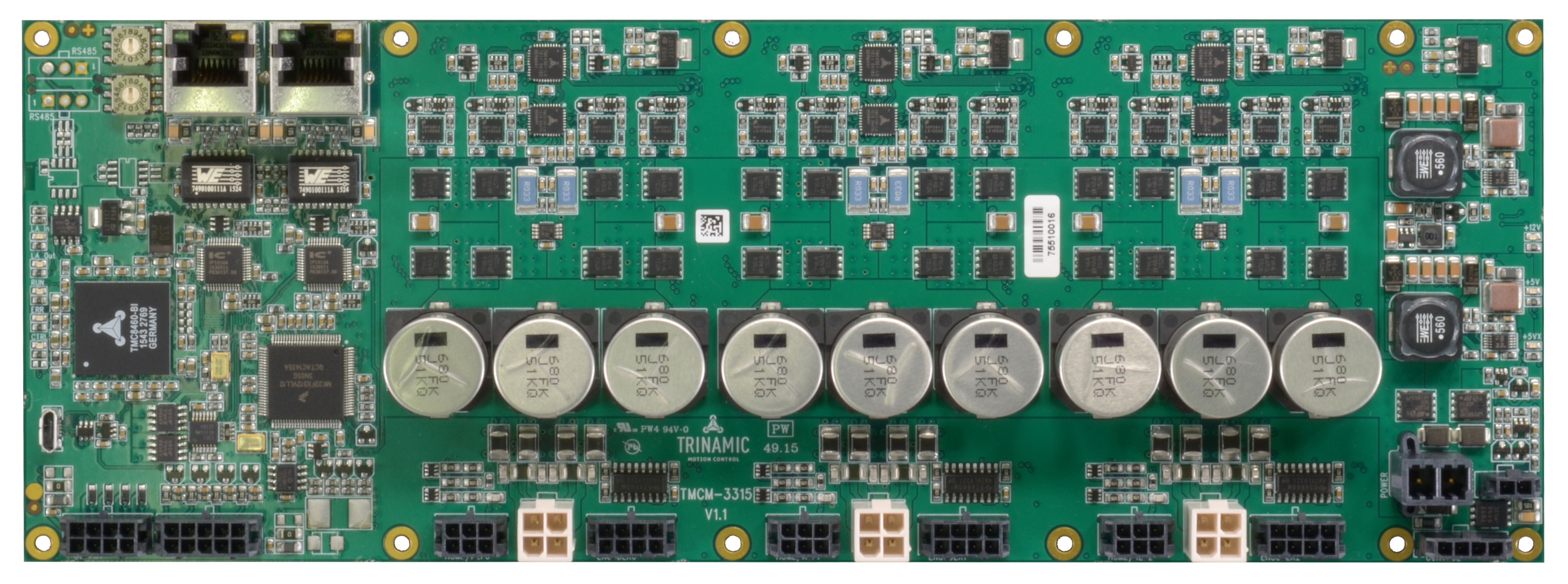
Stepper Modules: Slot-Type
| P/N |
Interface |
Voltage |
Phase Current (rms)
cont. / peak |
Ramp |
Motor Type |
Encoder Input |
Options |
Features |
Board Size |
Datasheets |
| TMCM-1230 |
USB-C
RS485 |
10...30V |
5A |
S-Shaped
Linear
SixPoint™ |
Stepper
2-phase
bipolar |
ABN |
End- & Ref.-Switch IN: 2x STOP
General Purpose IN (digital): 2x 5V
General Purpose IN (analog): 2x 0...5V, 12bit
Address IN (CAN-bus): 4x |
stallGuard2™
coolStep™
spreadCycle™
microPlyer™
stealthChop™ |
80 x 40/
45 x 7 mm |
|
| TMCM-1231 |
USB-C
RS485 |
10...52V |
6,5A |
S-Shaped
Linear
SixPoint™ |
Stepper
2-phase
bipolar |
ABN |
End- & Ref.-Switch IN: 2x STOP
General Purpose IN (digital): 2x 5V
General Purpose IN (analog): 2x 0...5V, 12bit
Address IN (CAN-bus): 4x |
stallGuard2™
coolStep™
spreadCycle™
microPlyer™
stealthChop™ |
80 x 40/
45 x 7 mm |
|
| TMCM-1637 |
RS485
CAN |
10...30V
& 5V |
5A / 10A |
Linear |
3-Phase BLDC, PMSM
2-Phase Stepper
1-Phase DC |
- |
End- & Ref.-Switch IN: 3x
General Purpose IN (digital): 2x
General Purpose IN (analog): 2x 0...5V, 12bit
Address IN (CAN-bus): 4x |
- |
80 x 40/
45 x 7 mm |
|
| TMCM-1638 |
RS485
CAN |
10...52V
& 5V |
7A / 10A |
Linear |
3-Phase BLDC, PMSM
2-Phase Stepper
1-Phase DC |
- |
End- & Ref.-Switch IN: 3x
General Purpose IN (digital): 2x
General Purpose IN (analog): 2x 0...5V, 12bit
Address IN (CAN-bus): 4x |
- |
80 x 40/
45 x 7 mm |
|
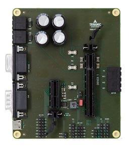
| TMCM-BB1 |
USB-C
RS485
CAN |
24 or 48V |
- |
- |
- |
- |
Controller Slots: 1
Driver Slots: 1 |
- |
t.b.d. |
|
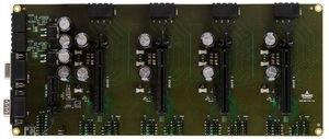
| TMCM-BB4 |
USB-C
RS485
CAN |
24 or 48V |
- |
- |
- |
- |
Controller Slots: 1
Driver Slots: 4 |
- |
t.b.d. |
|
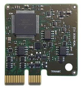
| TMCM-0930 |
USB-C
RS485
CAN |
5V |
- |
- |
- |
- |
- |
- |
40 x 45mm |
|
Stepper Modules: Multi Axis
Family Properties:
*TMCM Modules without FirmWare option are using the Trinamic Motion Control Language TMCL™.
Website
Stepper Modules: Closed Loop
Family Properties:
- max. µStep Resolution: 256
- Voltage range: 12...52V
Website
Stepper Modules: EtherCAT
*TMCM Modules without FirmWare option are using the Trinamic Motion Control Language TMCL™.
Website
BLDC-Modules
Plug-In Modules
| P/N |
Interface |
Axes |
Voltage |
Phase
Current
(rms) |
Feedback |
Features |
Size
[mm] |
Datasheet
/Web |
| BB-163x |
USB
RS485
CAN
RS232 |
1 |
12...55V |
10A |
- |
- |
120 x 90mm |
|
| TMCM-1637 |
RS485
CAN |
1 |
10...30V
& 5V |
5A
7A |
Incremental encoder
Digital HALL sensors
Analog encoder
absolute SPI & SSI encoders |
- |
80 x 40mm
45 x 7mm |
|
| TMCM-1638 |
RS485
CAN |
1 |
10...52V
& 5V |
7A
10A |
Incremental encoder
Digital HALL sensors
Analog encoder
absolute SPI & SSI encoders |
- |
80 x 40mm
45 x 7mm |
|
| TMCM-BB1 |
USB-C
RS485
CAN |
1 |
24V
48V |
- |
- |
- |
t.b.d. |
|
| TMCM-BB4 |
USB-C
RS485
CAN |
1 |
24V
48V |
- |
- |
- |
t.b.d. |
|
| TMCM-1617-BB |
RS485
CAN |
- |
8...28V |
- |
HALL sensors |
- |
85 x 55mm |
|
| TMCM-1617 |
RS485
CAN
EtherCAT |
- |
8...28V |
4A
18A |
Incremental encoder
Digital HALL sensors
Analog encoder |
- |
36.8 x 26.8 x 11.1mm |
|
| TMCM-1633 |
RS232
CAN
(CANopen) |
1 |
12...48V |
10A |
ABN encoder
HALL sensors
sensorless |
short-2-GND detect.
brake-before-make
slope control
FOC |
50x92mm
piggy
board |
|
Motor Mountable
| P/N |
Interface |
Axes |
Voltage |
Phase
Current
(rms) |
Feedback |
Features |
Size
[mm] |
Datasheet
/Web |
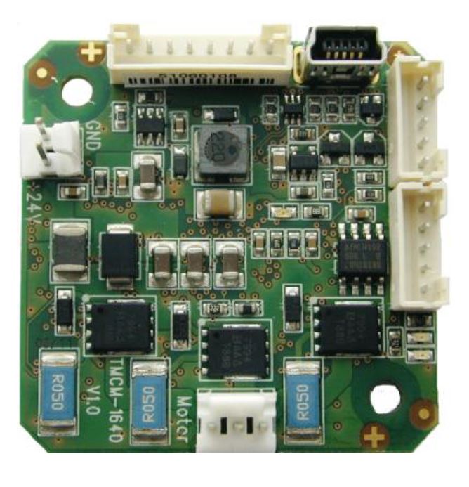
TMCM-1640
|
RS485
USB |
1 |
12...28V |
7A |
ABN encoder
HALL sensors
sensorless |
short-2-GND
detect.
brake-before-make
slope control
FOC |
42x42mm |
|
Website
Mechatronic PANdrive Solutions
Stepper Motor with Motion Controller & Driver
Properties:
- max. µStep Resolution: 256
- Open Loop
- Linear Ramps
|
Product Overview PANdrive |
PANdrive™
Family |
Interface |
Supply |
Model |
Holding
Torque |
sensOstep
Encorder
res. |
Features |
FW
option* |
Flange
Size |
Datasheet
/Web |
| PD28-1021 |
RS485
STEP/DIR |
9...28V |
1
3 |
0,06Nm
0,12Nm |
1024ppr |
stallGuard2™
coolStep™
spreadCycle™
microPlyer™ |
- |
NEMA 11
28x28mm |
|
| PD42-1140 |
CAN
RS485
USB |
9...28V |
1
2
3
4 |
0,22Nm
0,36Nm
0,44Nm
0,70Nm |
1024ppr |
stallGuard2™
coolStep™
spreadCycle™ |
TMCL
CAN
open |
NEMA17
42x42mm |
|
| PD42-1141 |
RS485
USB
STEP/DIR |
9...28V |
1
2
3 |
0,27Nm
0,35Nm
0,40Nm |
- |
stallGuard2™
coolStep™
spreadCycle™
microPlyer™ |
- |
NEMA17
42x42mm |
|
| PD42-1240 |
CAN RS485 USB |
10...30V |
1
2
34 |
0,22Nm 0,36Nm 0,44Nm 0,70Nm |
1024ppr |
stallGuard2™ coolStep™
spreadCycle™ stealthChop2™ |
TMCL CAN open |
NEMA17 42x42mm |
|
| PD57-1160 |
CAN
RS485
USB
STEP/DIR |
9...51V |
1
2 |
0,55Nm
1,01Nm |
1024ppr |
stallGuard2™
coolStep™
spreadCycle™
microPlye™r |
TMCL
CAN
open |
NEMA23
57x57mm |
|
PD57-1161
|
RS485
USB
STEP/DIR |
10...30V |
1
2 |
0,55Nm
1,01Nm |
1024ppr |
stallGuard2™
coolStep™
spreadCycle™
microPlyer™ |
- |
NEMA23
57x57mm |
|
PD57-1260
|
CAN
RS485
USB
STEP/DIR |
12...54V |
1
2 |
0,55Nm
1,01Nm |
1024ppr |
stallGuard2™
coolStep™
spreadCycle™
stealthChop2™
microPlyer™ |
TMCL
CAN
open |
NEMA23
57x57mm |
|
| PD60-1160 |
CAN
RS485
USB
STEP/DIR |
9...51V |
3
4
|
2,1Nm
3,1Nm |
1024ppr |
stallGuard2™
coolStep™
spreadCycle™
microPlyer™ |
TMCL
CAN
open |
NEMA24
60x60mm |
|
| PD60-1161 |
RS485
USB
STEP/DIR |
10...30V |
3
4 |
2,1Nm
3,1Nm |
1024ppr |
stallGuard2™
coolStep™
spreadCycle™
microPlyer™ |
- |
NEMA24
60x60mm |
|
| PD60-1260 |
CAN
RS485
USB
STEP/DIR |
12...54V |
3
4 |
2,1Nm
3,1Nm |
1024ppr |
stallGuard2™
coolStep™
spreadCycle™
stealthChop2™
microPlyer™ |
TMCL
CAN
open |
NEMA24
60x60mm |
|
| PD86-1180 |
CAN
RS485
RS232
USB
STEP/DIR |
18...55V |
3 |
7,0Nm |
256ppr |
stallGuard2™
coolStep™
spreadCycle™
microPlyer™ |
TMCL
CAN
open |
NEMA34
86x86mm |
|
*PANdrives without FirmWare option are using the Trinamic Motion Control Language TMCL™.
Ordercodes:
PDxx-"Model"-1xxx-"Option"
Firmware-Options:
-TMCL (Trinamic Motion Control Language)
-CANopen (CANopen protocoll)
Cable loomes have to be ordered separately!
PANdrive Manuals
Stepper & BLDC Motors
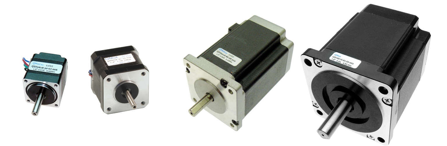
QMot Label
2-Phase Hybrid Stepper Motors (High Torque)
Selection of standard stepper motors with a currents fitting to the Trinamic driver products.
Low variety - good availability - short lead time
Common Properties:
| P/N |
Flange
Size
(NEMA) |
Flange
Size
(mm) |
Motor
Length |
Phase
Current |
Holding
Torque |
Datasheet
/Web |
QSH2818-32-07-006
|
11 |
28x28mm |
32mm |
0,67A |
0,006 Nm |
|
| QSH2818-51-07-012 |
11 |
28x28mm |
51mm |
0,67A |
0,012Nm |
|
| QSH4218-35-10-027 |
17 |
42x42mm |
35mm
|
1,0A
|
0,27Nm
|
|
| QSH4218-41-10-035 |
17 |
42x42mm |
41mm
|
1,0A |
0,35Nm
|
|
| QSH4218-51-10-049 |
17 |
42x42mm |
51mm
|
1,0A |
0,49Nm
|
|
| QSH4218-47-28-040 |
17 |
42x42mm |
47mm
|
2,8A
|
0,40Nm
|
|
QSH5718-41-28-055
|
23
|
57x57mm |
41mm
|
2,8A |
0,55Nm |
|
| QSH5718-51-28-101 |
23 |
57x57mm |
51mm
|
2,8A |
1,01Nm |
|
| QSH5718-56-28-126 |
23 |
57x57mm |
56mm
|
2,8A |
1,26Nm |
|
| QSH5718-76-28-189 |
23 |
57x57mm |
76mm
|
2,8A |
1,89Nm |
|
QSH6018-45-28-110
|
24 |
60x60mm |
45mm
|
2,8A |
1,10Nm |
|
| QSH6018-56-28-165 |
24 |
60x60mm |
56mm
|
2,8A |
1,65Nm |
|
| QSH6018-65-28-210 |
24 |
60x60mm |
65mm
|
2,8A |
2,10Nm |
|
| QSH6018-86-28-310 |
24 |
60x60mm |
86mm
|
2,8A |
3,10Nm |
|
| QSH8618-96-55-700 |
34
|
86x86mm |
96mm
|
5,5A
|
7,00Nm |
|
Datasheets
3-Phase BLDC Motors
Selection of standard BLDC motors with a currents fitting to the Trinamic driver products.
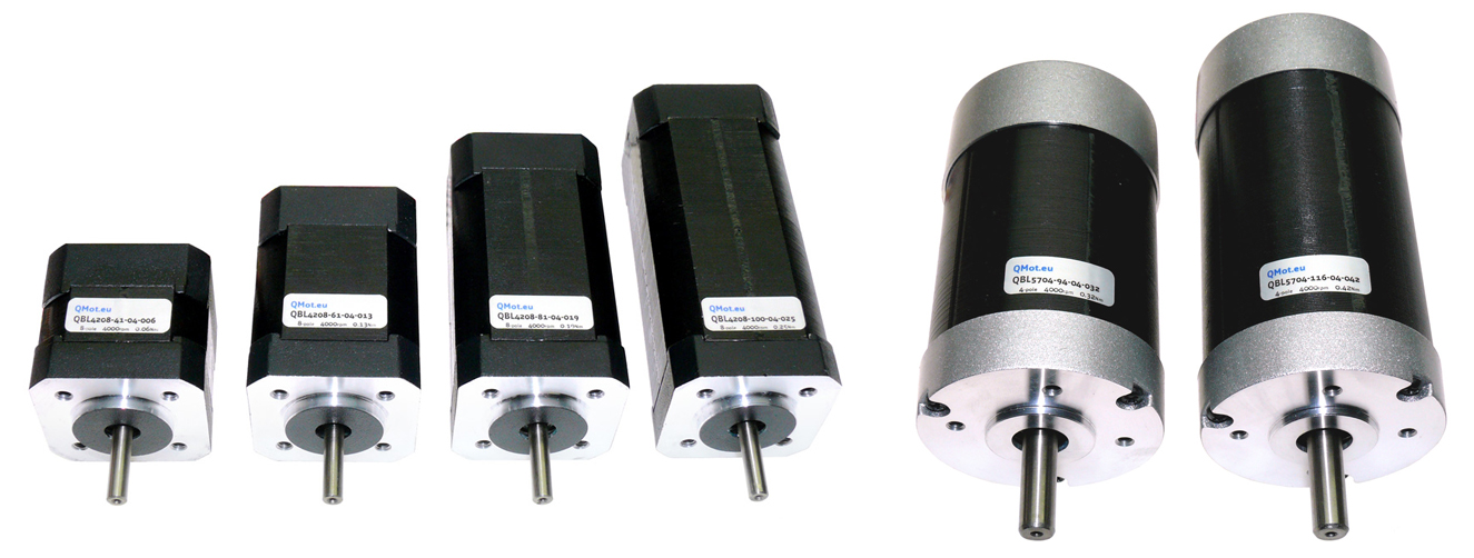
Common Properties:
| P/N |
Flange |
No. of
Poles |
Motor
Length |
Torque |
Phase Current
(peak) |
Datasheet
/Web |
| QBL4208-41-04-006 |
42x42mm
|
8
|
41mm
|
0,0625Nm |
5,4A |
|
| QBL4208-61-04-013 |
42x42mm |
8
|
61mm
|
0,125Nm |
10,4A |
|
| QBL4208-81-04-019 |
42x42mm |
8
|
81mm
|
0,185Nm |
15,5A |
|
| QBL4208-100-04-025 |
42x42mm |
8
|
100mm
|
0,25Nm |
20A |
|
| QBL5704-94-04-032 |
d= 57mm |
4
|
94mm
|
0,32Nm |
16,5A |
|
| QBL4208-116-04-042 |
d= 57mm |
4
|
116mm
|
0,42Nm |
20,5A |
|
Datasheets
Position & Angle Sensors
Optical Incremental Encoders
The TMCS-Family is a series of high resolution incremental optical encoders for stepper motors and 3-phase BLDC motors.
| P/N |
Size |
Resolution
[lines]
[increments] |
Voltage |
Signal
Level |
Shaft/Hollow
Diameter |
Datasheet
/Web |
TMCS-20
|
20mm
|
8192
32768
|
5V
|
TTL
differential
|
4mm
|
|
TMCS-28-5
|
28mm
|
10000
40000
|
5V
|
TTL
differential
|
5mm
|
|
TMCS-28-6.35
|
28mm
|
10000
40000
|
5V
|
TTL
differential
|
6,35mm
|
|
TMCS-40
|
40mm
|
10000
40000 |
5V
|
TTL
differential
|
6,35mm |
|
TRINAMIC Technologies / Patents

TRINAMIC’s patented sensorless stall detection stallGuard™ enables customers to detect mechanical overload
conditions and stall conditions without external sensors, by measuring the load at a predefined point where a step loss has not yet occurred. Thus, it
eliminates the need for reference or end switches. This reduces cost and complexity of applications, where a reference point is required.
When compared to pure mechanical referencing, stress on the mechanic and noise is reduced.

Improved version of the successfull stallGuard™
feature. stallGuard2™ is the world’s first sensorless high resolution load detection implemented in a
standard stepper motor driver. This gives the user easy and cost effective real time feedback of his application. It enables to scan the motion system
without additional sensors. This can help to find the right motor and mechanics during development phase or to detect abrasion or mechanical stiffness.
stallGuard2 provides an accurate measurement of the load on the motor. It can be used for stall detection as well as other uses at loads below those
which stall the motor, such as coolStep load adaptive current reduction. This gives more information on the drive allowing functions like sensorless
homing and diagnostics of the drive mechanics.
Whitepaper: Flüsterleise Schrittmotoren
Sensorless load dependent current control using the stallGuard2™ feature. First time coolStep™
enables to drive a stepper motor in a energy efficient way. Up to now stepper motors are driven with constant current. The new TMC260, TMC261 and
TMC262 stepper motor driver series detects the actual load of the motor and adjusts the current accordingly. This eliminates the safety current margin
and also allows to boost the motor. This efficiency avoids stall and step loss to improve the reliability of the entire system.
Classic stepper motor control with constant current:
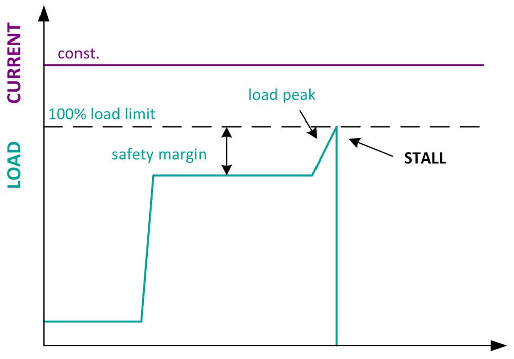
- The current is constant and not dependent on the load of the motor
- With a constant current there is a fixed load limit
- With low load the current heats up the motor
- As soon as a torque peak exceeds the load limit, a stall or step loss occurs
- Usually a high safety marging is used to avoid a stall or step loss
Stepper motor control with coolStep™ adapted current:
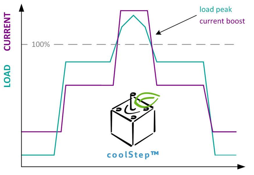
- As soon as the load value reaches a programmed limit the current rises
- The motor current can temporarilly exceed the nominal value
- There is no fixed load limit
- The motor gets only the needed current
- With coolStep™ up to 75% energy can be saved
- No safety margin is needed
- Higher system reliability
Whitepaper: Flüsterleise Schrittmotoren
spreadCycle™ PWM Chopper
TRINAMIC patented constant T(off) chopper scheme. The PWM chopper is used for the current control of the stepper motor. The supply voltage is swiched
on (ON) and off (OFF) in a way that the current in the motor is getting the requested wave form.
Using the spreadCycle™ chopper the micro step current sine wave is always well formed with a smooth zero
crossing. Due to this effect the stepper motor moves smoothly and without vibration.
All the coolStep™ drivers include this technology.
The classic constant T(off) chopper scheme:
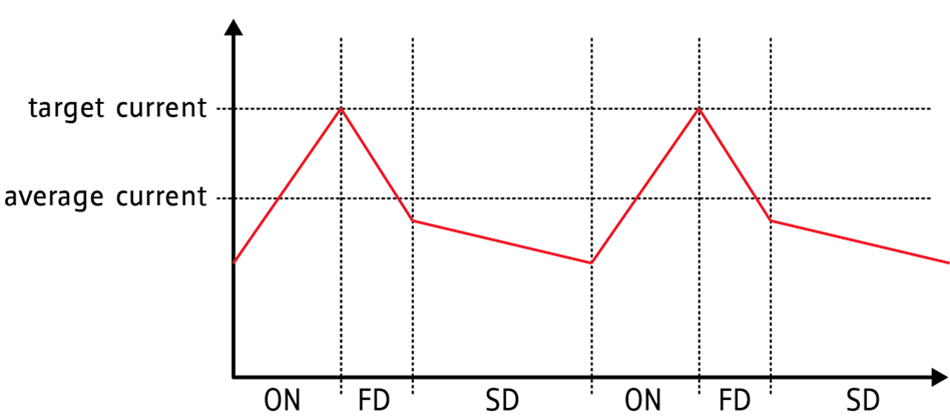
The classic constant T(off) time chopper switches the current ON until the target current is reached.
The OFF phase starts with a programmable fixed portion of fast decay (FD) followed by slow decay (SD).
The current ripple ist not symmetric.
As the current is going up only until the target current, the mean current value is always lower than the target:
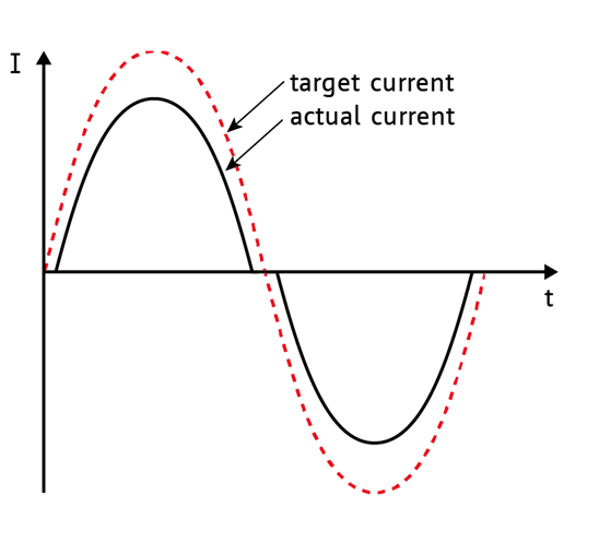
The effect is a plateau during the current zero crossing. At slow motor speed this plateau means that the motor stops for a short time every two full steps.
The TRINAMIC spreadCycle™ hysteresis chopper scheme:
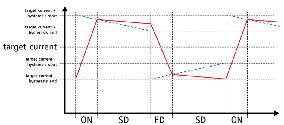
The spreadCycle™ chopper scheme is a precise and simple to use chopper principle, which automatically
determines the optimum fast decay portion for the motor. The result is a symmetrical shape with a low current ripple and a precise current zero crossing.
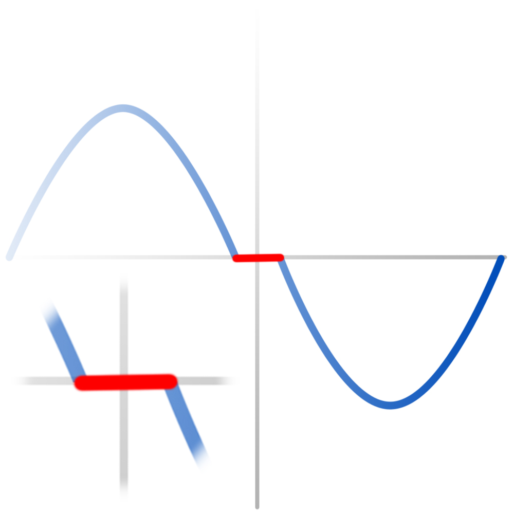
Waveform examples with different PWM chopper modes
Classic constant T(off) chopper:
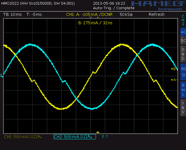
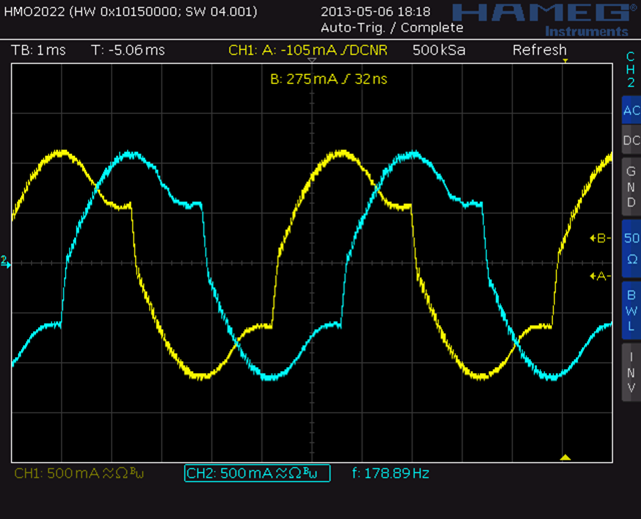
slow speed effect: zero crossing
high speed effect: back EMF
TRINAMIC spreadCycle™ constant T(off) chopper:
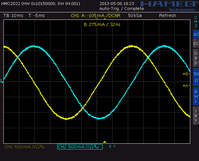
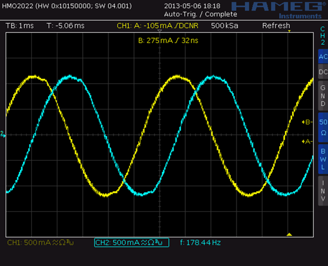
slow speed
high speed
Whitepaper: Flüsterleise Schrittmotoren
microPlyer™
Microstep interpolator for obtaining increased smoothness with high-res microstepping over a low-end STEP/DIR interface. The microPlyer™
STEP pulse interpolator brings the smooth motor operation of high-resolution microstepping to applications originally designed for coarser stepping.
External step pulses are converted to multiple internal microsteps to benefit from advantages of high resolution microstep like resonance
suppression and increased output torque at low speeds.
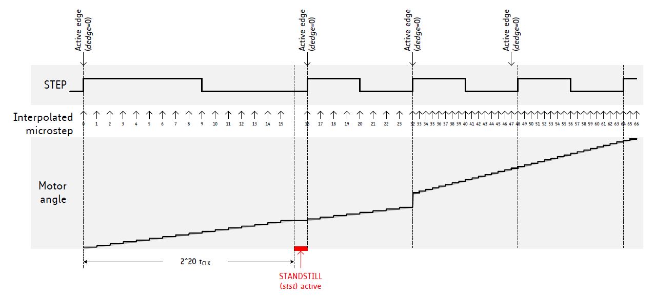
microPlyer microstep interpolation with rising STEP frequency (Example: 16 to 256)
For some drivers (TMC26x, TMC5072) the interpolation rate is fixed from 16 to 256.
Whitepaper: Flüsterleise Schrittmotoren

Flyer:
dcStep
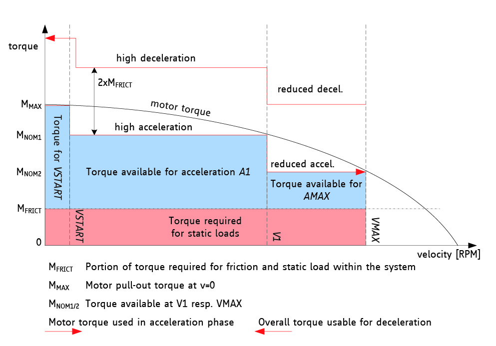
dcStep™ closes the gap between fully featured closed loop stepper motor drives and cost efficient open loop
systems. While most open loop Stepper Drives will loose steps in an overload situation, dcStep™ drives will
reduce the speed in order to overcome the resistance. Thus the integrity of the position counter is always given. With dcStep™
a stepper motor will act similar as a DC motor with regards to energy efficiency. dcStep™ allows for auto
ramping and turning the motor as fast as possible in the actual load situation.
The unique feature dcStep™ allows the motor to run near its load limit and at its velocity limit without
losing steps. If the mechanical load on the motor increases to the stalling load, the motor automatically decreases its velocity to a point where it can
still drive the load. With this feature, the motor will never stall. In addition to its increased torque at a lower velocity, dynamic inertia will
allow the motor to overcome mechanical overloads by decelerating. dcStep™ directly integrates with the ramp generator, so that the target position
will be reached, even if the motor velocity needs to be decreased due to increased mechanical load. A dynamic range of up to factor 10 or more can be
covered by dcStep™ without any step loss. By optimizing the motion velocity under high load situations, this
feature further enhances overall system efficiency.
- Motor does not loose steps in overload conditions
- Application works as fast as possible
- Highest possible acceleration automatically
- Highest energy efficiency at speed limit
- Highest possible motor torque using fullstep drive
- Cheaper motor does the job
Whitepaper: Flüsterleise Schrittmotoren
chopSync™
The patented chopSync™ feature allows very high velocity operation of stepper motors using the standard
TRINAMIC stepper motor drivers with constant frequency chopper. This is achieved by reducing resonances
occurring when operating the motor at velocities where the EMF voltage exceeds the level of the supply voltage. With chopSync™,
motor velocities of several 1000 RPM can be reached.
Whitepaper: Flüsterleise
Schrittmotoren
chopSync2™
chopSync2™ is an alternative add-on concept for spreadCycle™ chopper
and constant off time chopper to optimize motor noise at low velocities. When using stealthChop™ for low
velocity operation, chopSync2™ is not applicable. While a frequency adaptive chopper like spreadCycle™
provides excellent high velocity operation, in some applications, a constant frequency chopper is preferred rather than a frequency adaptive chopper.
This may be due to chopper noise in motor standstill, or due to electro-magnetic emission. chopSync2™
provides a means to synchronize the choppers for both coils with a common clock, by extending the off time of the coils. It integrates with both
chopper principles. However, a careful set up of the chopper is necessary, because chopSync2™ can just
increment the off times, but not reduce the duration of the chopper cycles themselves. Therefore, it is necessary to test successful operation best
with an oscilloscope. Set up the chopper as detailed above, but take care to have chopper frequency higher than the chopSync2™
frequency. As high motor velocities take advantage of the normal, adaptive chopper style, chopSync2™ becomes
automatically switched off using the VHIGH velocity limit programmed within the motion controller
Whitepaper: Flüsterleise
Schrittmotoren
stealthChop™
Voltage controlled mode with additional current control. Ultra low noise, premium smoothness motion.
Flyer:
stealthChop™
New patent pending stealthChop™ technology delivers exceptionally quiet stepper motor performance
The new technology significantly reduces the noise of conventional stepper motor operation.
Motors operating at low speed exhibit a phenomenon known as magnetostriction, which causes an audible low frequency ‘hum.’ This
low-frequency noise is well known as the 60Hz hum that emanates from transmission lines and transformers. Trinamic’s stealthChop™
minimizes magnetostriction by implementing a PWM algorithm that relies predominantly on voltage modulation for motor control at lower speeds. This
technology minimizes PWM current fluctuation, which is the primary cause of low-speed hum.
Stepper motors used in automation must respect the needs of their human overlords. The continuous noise of individual stepper motors in a laboratory
environment may be rather distracting, and the din from hundreds of stepper motors in an industrial implementation can be deafening.
Customers asked Trinamic to perfect a commutation scheme for lower step frequencies that reduces noise. stealthChop™
is self tuning, easy to use and has an automated switch to transition to higher frequencies.
Noise limitations are especially desirable in applications that normally occur in close proximity to human operators, in applications where multiple
stepper motors are in use, in video surveillance applications where installations near walls and ceilings amplify noise, and in consumer
applications, like home automation and air conditioning, where users expect minimal noise.
TRINAMIC devices that implement this new stealthChop™
technology have achieved measured noise levels 10 dB below traditional stepper motor drive ICs.


Jitter: spreadCycle vs. stealthChop
Whitepaper: Flüsterleise Schrittmotoren
stealthChop2™
stealthChop2™
is an advanced version of the stealthChop™
technology and eliminates the disadvantage of the limited acceleration capability.
At the first move, the driver measures the inner resistance and the back EMF of the Motor and saves it. With these data, the current will be controlled
immediately so that there are no changes during acceleration. The motor always gets his ideal current.
Drivers with stealthChop2™:
Whitepaper: Flüsterleise Schrittmotoren
Content
hallFX™
Hall effect sensor emulatuion for BLDC motors.
PANdrive™
TRINAMIC brand name for a Motor and Controller/Driver Electronics combined as mechatronic solution.

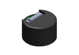
sensOstep™
is the TRINAMIC brand name for an integrated magnetic absolute encoder.
On the rear shaft of the motor there is mounted a small magnet. On the controller/driver board a hall sensor IC is mounted.
The resolution of the sensOstep™
encoder is given in ppr (positions per rotation/revolution).
TMCL™ - Trinamic Motion Control Language
The TMCL™ is a programming language dedicated to motion control applications. The software includes commands for
moving one or more motor axes at certain velocities or to certain positions and for setting all relevant parameters of the motion controller. It is
possible to access additional general purpose digital and analog inputs and outputs. TMCL™ is available on most
TRINAMIC modules with integrated motion controller. Program development is supported by the TMCL-IDE* – a PC
based integrated development environment which is available free of charge.
* IDE = Integrated Development Environment
TMCL IDE 3.0 upgrade adds comprehensive controls for parameterization, evaluation & test
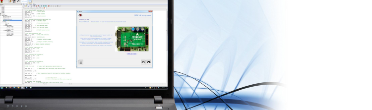
Trinamic has upgraded its popular TMCL Integrated Development Environment to version 3.0. This latest version of the Trinamic IDE features new, intuitive
tools to aid programming and parameterization for Trinamic Board level products, plus advanced tools for device status logging and evaluation. The
GUI and Parameterization Wizards have been expanded and enhanced to provide even easier user operation. The new IDE also improves bus interface
connectivity for all busses supported by Trinamic Modules.
The PC-based TMCL IDE 3.0 can be downloaded free-of-charge.
https://www.trinamic.com/support/software/tmcl-ide/
For remote control applications the TMCL commands are defined in a 9-byte protocoll that can be send over a
serial communication interface like USB, RS232, RS485 etc.
Trinamic Products with TMCL™:
Trinamic Motion Control Modules
PANdrive™ Mechatronics
IC Evaluationboards with modular Concept using "Startrampe" or "Landungsbrücke"
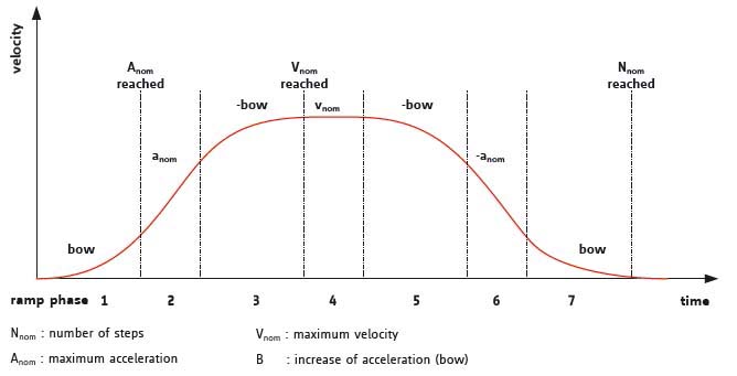
Linear / trapezoidal acceleration ramp:
Driving a stepper motor at velocities higher than its physical start/stop frequency requires a defined acceleration. For the great majority of
positioning applications linear ramping profiles are sufficient.
 Index
Index
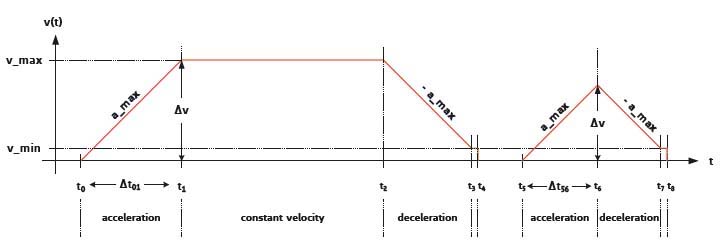
sixPoint™ acceleration ramp
TRINAMICs unique sixPoint™ acceleration ramp allows for faster accelerations by starting the linear
ramping phase not from zero speed but from a configurable start/stop speed. By adding additional breaks in the ramping profile also a jerk
reduction is possible. This way applications, that are too sensitive for linear ramping but do not allow for high cost and complexity of S-shape controllers can be easily controlled.
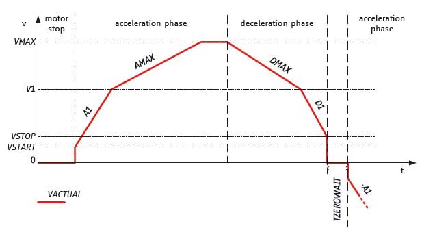
S-shape/sinusoidal acceleration ramp:
For high speed positioning as well as for handling of jerk sensitive goods or objects with extensive inertia sinusoidal or S-shaped ramping profiles might be necessary.
Trinamic S-shape ramp motion controllers allow for an alteration of all motion parameters on the fly.
Content
Interfaces and Protocols
SPI - Serial Peripheral Interface
The Serial Peripheral
Interface or SPI bus is a synchronous serial data link, a de facto standard, named by
Motorola, that operates in full duplex mode. It is used for short distance, single master communication, for example in embedded systems, sensors, and SD cards.
Devices communicate in master/slave mode where the master device initiates the data frame. Multiple slave devices are allowed with individual slave
select lines. Sometimes SPI is called a four-wire serial bus, contrasting with three-, two-, and one-wire
serial buses. SPI is often referred to as SSI (Synchronous Serial Interface).
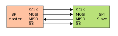
The SPI bus specifies four logic signals:
SCLK : Serial Clock (output from master).
MOSI : Master Output, Slave Input (output from master).
MISO : Master Input, Slave Output (output from slave).
SS : Slave Select (active low, output from master).
Source: www.wikipedia.org
Content
Step/Direction
Step/Direction, Pulse/Direction or Clock/Direction.
The Direction signal set the direction of rotation and each pulse on the Step
signal causes the controller to move the motor one step in that direction. The controller translates these signals into different patterns of current
flow in the coils, which result in the moment of the motor.
The pulse frequency of the Step signal defines the motor speed. Depending on the setting of the Stepper Motor Driver the Step signal is taken as
fullstep, halfstep or microstep signal.
SingleWire UART
New interface that TRINAMIC introduced for stepper motor controller & driver to decrease the number of bus lines for multi axis systems.
The single wire interface allows differential operation similar to RS485 or single wire interfacing. It can be driven by any standard UART. No baud rate configuration is required.
IIC or I²C
I²C (Inter-Integrated Circuit), pronounced I-squared-C, is a multi-master, multi-slave, single-ended, serial
computer bus invented by Philips Semiconductor, known today as NXP Semiconductors, used for attaching low-speed peripherals to computer motherboards and embedded systems.
Alternatively I²C is spelled I2C (pronounced I-two-C) or IIC (pronounced I-I-C).
Since October 10, 2006, no licensing fees are required to implement the I²C protocol. However, fees are still required to obtain I²C
slave addresses allocated by NXP.
Some companies are using also the term TWI (Two-Wire-Interface).
I²C uses only two bidirectional open-drain lines, Serial Data Line (SDA) and Serial Clock Line (SCL), pulled up with resistors.
Typical voltages used are +5 V or +3.3 V although systems with other voltages are permitted.
Analog / Parallel
Classic interface for stepper motor driver.
For every motor phase thre are two inputs: an analog value for the current (Phase A+B) and the direction of the current of the phase (SignA+B).
Using the analog/parallel interface it is necessary to generate an analog value for the motor current.
ABN / ABZ Encoder
Common interface for incremental rotary encoders
An incremental rotary encoder provides cyclical outputs (only) when the encoder is rotated.
The fact that incremental encoders use only two sensors does not compromise their accuracy. One can find in the market incremental encoders with up to 10,000 counts per revolution,
or more.
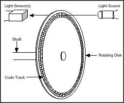

The two output (A & B) wave forms are 90 degrees out of phase, which is what quadrature means. These signals are decoded to produce a count up pulse
or a count down pulse. For decoding in software, the A & B outputs are read by software, either via an interrupt on any edge or polling, and the
above table is used to decode the direction. For example, if the last value was 00 and the current value is 01, the device has moved one half step in
the clockwise direction. The mechanical types would be debounced first by requiring that the same (valid) value be read a certain number of times
before recognizing a state change.
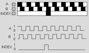
There can be an optional third output: reference or "index", which happens once every turn. This is used when there is the need of an absolute
reference, such as positioning systems. The index output is usually labeled Z (zero) or N (null).
SSI Encoder
Synchronous Serial Interface (SSI) is a widely used serial interface standard for industrial applications
between a master (e.g. controller) and a slave (e.g. sensor). SSI
is based on RS-422 standards and has a high protocol efficiency in addition to its implementation over various hardware platforms, making it very
popular among sensor manufacturers. SSI was originally developed by Max Stegmann GMBH in 1984 for transmitting the position data of absolute
encoders – for this reason, some servo/drive equipment manufacturers refer to their SSI port as a "Stegmann
Interface". It was formerly covered by the German patent DE 34 45 617 which expired in 1990. It is very suitable for applications demanding reliability
and robustness in measurements under varying industrial environments.
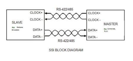
The CLOCK and DATA signals are transmitted according to RS-422 standards. RS-422, also known as ANSI/TIA/EIA-422-B, is a technical standard that
specifies the electrical characteristics of the balanced voltage digital interface circuit. Data is transmitted using balanced or differential
signalling i.e. the CLOCK and DATA lines are basically twisted pair cables.
BISS Encoder

The open source BiSS Interface (bidirectional/serial/synchronous) is based on a protocol which implements a
real time interface. It enables a digital, serial and secure communication between controller, sensor and actuator. The BiSS protocol is designed in B
mode and C mode (continuous mode). It is used in industrial applications which require transfer rates, safety, flexibility and a minimized
implementation effort. The BiSS
interface has roots in SSI and a simplified INTERBUS; competing solutions are the proprietary standards of Hiperface and EnDat.
BiSS is hardware compatible to the standard SSI (Serial Synchronous Interface) and can moreover,
even in the unidirectional implementation - for example BiSS C (unidirectional) -
learn transmission times, thus clocking considerably faster depending on the line drivers used (up to 10 MHz with RS422 and 100 MHz with LVDS). BiSS
can request processing times and is suitable for safety applications thanks to its CRC, error messaging and warning features. BiSS can also be used in
sensor buses and can operate actuators via two additional lines.
CAN
CAN bus (for Controller Area
Network) is a vehicle bus standard designed to allow microcontrollers and devices to
communicate with each other within a vehicle without a host computer.
CAN bus is a message-based protocol, designed specifically for automotive applications but now also used in other
areas such as aerospace, maritime, industrial automation and medical equipment.
Development of the CAN bus started originally in 1983 at Robert Bosch GmbH. The protocol was officially
released in 1986 at the Society of Automotive Engineers (SAE) congress in Detroit, Michigan. The first CAN controller chips, produced by Intel and
Philips, came on the market in 1987. Bosch published the CAN 2.0 specification in 1991.
Source: www.wikipedia.org
The CAN bus defines only the electrical interface, but not a protocol.

CANopen is a communication protocol and device profile specification for embedded systems used in
automation. In terms of the OSI model, CANopen implements the layers above and including the network layer. The CANopen standard consists of an
addressing scheme, several small communication protocols and an application layer defined by a device profile. The communication protocols have support
for network management, device monitoring and communication between nodes, including a simple transport layer for message segmentation/desegmentation.
The lower level protocol implementing the data link and physical layers is usually CAN, although devices using some other means of
communication (such as Ethernet Powerlink, EtherCAT) can also implement the CANopen device profile.
The basic CANopen device and communication profiles are given in the CiA 301 specification released by "CAN in Automation". Profiles for more specialized
devices are built on top of this basic profile, and are specified in numerous other standards released by "CAN in Automation",
such as CiA 401 for I/O-modules and CiA 402 for motion control.
Source: www.wikipedia.org
Link to CAN in Automation: www.can-cia.org
EtherCAT - Ethernet for Control
Automation Technology - is an open high performance Ethernet-based fieldbus system, originally developed by Beckhoff. The development goal of EtherCAT
was to apply Ethernet to automation applications which require short data update times (also called cycle times) with low communication
jitter (for synchronization purposes) and low hardware costs.
Source: www.wikipedia.org
Link to EtherCAT Group: www.ethercat.org